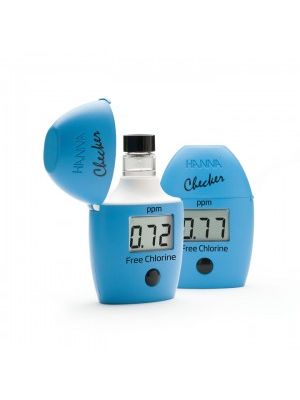
HI720224-2 Conductivity /TDS Controller - 2 setpoints and analog output (Used with Inductive Probe)

Product information "HI720224-2 Conductivity /TDS Controller - 2 setpoints and analog output (Used with Inductive Probe)"

Autoranging EC or TDS and temperature for EC/TDS
Automatic temperature compensation for EC/TDS
Fully customizable: automatic/manual/no temperature compensation; Selectable reference temperature between 02 and 25 C; Selectable temperature coefficient between 0.00 to 20.00%/C; Selectable temperature compensation curve between linear, salinity or user definable, Selectable TDS factor between 0.01 to 1.00
Temperature compensation curve selectable between linear, salinity or user defined
TDS factor selectable between 0.01 to 1.00
Supports inductive EC probe with built-in or external Pt100/1000 sensor temperature
PID, PI, Proportional or On/off control for one or two set points
Sensor Check™ for real time detection of soiled EC/TDS probes
Damage test for temperature probe
Mount probes directly or use a digital transmitter for large distances
Logging of up to 100 system events
Control with up to 4 relays or analog output in 0-20 mA or 4-20 mA
Probe cleaning program performed automatically, by alarm or upon user request
Large variety of models to fit the user system requirements

HI 720 is a PID, PI, proportional or on/off EC/TDS controller with one or two set points and includes an inductive conductivity probe.

The measurement configuration settings and EC and TDS control are saved separately and permits users to switch between EC and TDS without losing settings. TDS or a specific user defined curve can be used for concentration.

Temperature is continuously monitored using a temperature sensor (Pt100 or Pt1000 type) with ATC of conductivity. Conductivity temperature compensation parameters are fully customizable: linear or non-linear temperature compensation, reference temperature and temperature coefficient. Users can define the specific curve of temperature compensation.

The working conductivity range is user selectable and the conductivity calibration in one point is performed in a value that corresponds to the measurement range.

One or two analog controller outputs (0-20 or 4-20 mA) can be configured for recording of pH/ORP or controlling (only for models with PID), and up to 4 relays can be used to control the process or be connected with alarm status. Controller status is visable with LED’s on the front panel and on LCD.
The controller logging feature can save the last 100 error, configuration, calibration and cleaning events. This information can be accessible from a PC through RS485 and HI 92500 software.
The controller also has a full auto diagnostic procedure. A cleaning procedure of the EC inductive probe is also available.

In-Line Cleaning

The cleaning feature allows an automatic cleaning action of the probe. To perform cleaning, the controller activates an external device (pump). Cleaning actions never take place if no relay is configured for cleaning. Cleaning can be of two types:

Simple cleaning: with water only, it can be triggered only by a timer (periodical cleaning) or by an error for which a cleaning action can be configured.
Advanced cleaning (optional): with water and detergent, it can be triggered by the following events:

Timer; Digital input or RS485 command (external trigger);
Timer and digital input or RS485 command (external trigger);
Timer masked by the digital input (i.e. disabled when the digital input is on);
Error for which a cleaning action can be configured

EC Inductive Probe Theory of Operation

This instrument allows conductivity measurements without any electrical contact between electrodes and process fluid. The measurement is based on inductive coupling of two toroidal transformers by the liquid.

The instrument supplies a high frequency, reference voltage to the “Drive Coil”, and a strong magnetic field is generated in the toroid.

The liquid passes through the hole in the toroid and can be considered as one turn secondary winding. The magnetic field induces a voltage in this liquid winding, the current induced in the flow is proportional to this voltage, and the conductance of the liquid one-turn winding is in accordance to Ohm’s law.

The conductance is proportional to the specific conductivity and a constant factor determined by the sensor geometry and installation.

The liquid also passes through the second toroid and therefore the liquid turn can be considered as a primary winding of the second toroidal transformer. The current in the liquid will create a magnetic field in the second toroid, and the induced current can be measured as an output.

The output current of this “receive coil” is therefore proportional to the specific conductivity of process liquid.

For an inductive cell, the cell constant is defined as the measured conductivity, obtained by making a loop through the sensor with a resistor R, multiplied by that R value.

The cell constant depends only on the sensor geometry. However, when the probe is immersed in a liquid, the induced current in the solution is affected by the piping or any other container where the probe is inserted. This effect is negligible when there is an area of at least 3 cm of liquid around the cell.

Otherwise, it is necessary to multiply measurements by the installation factor: Conductivity = (cell constant)(installation factor)/(measured resistance). The installation factor is < 1 for conductive piping/containers, and > 1 for nonconductive piping/containers.

Since this type of sensor has no electrodes, common problems such as polarization and contamination are eliminated and will not affect the performance of the electrodeless sensor.

Order Information:
Each HI 720224-2 model is supplied complete with mounting brackets and instructions.**Probe is sold separately


Specification :
Range Conductivity 0 to 2000 mS/cm (autoranging)
Temperature -30 to 130°C / -22 to 266°F
Resolution Conductivity 1 µS/cm (0 to 1999 µS/cm); 0.01 mS/cm (2.00 to 19.99 mS/cm); 0.1 mS/cm (20.0 to 199.9 mS/cm); 1 mS/cm (200 to 2000 mS/cm)
Temperature 0.1°C / 0.2°F
Accuracy @ 20°C Conductivity ±2% f.s.
Temperature ±0.5°C / ±1°F
Temperature
Compensation automatic or manual, -30 to 130°C
Temperature
Probe three-wire or two-wire Pt100 or Pt1000 sensor with automatic recognition and damage test
Digital Input digital transmitter, hold and advanced cleaning inputs
Digital Output one digital insulated contact closed upon hold mode
Analog Output one or two independent outputs; 0-22 mA (configuring as 0-20 mA or 4-20 mA)
Digital Serial Output RS485
Dosing Relay 1, 2, 3 or 4 electromechanical relays SPDT; 5A-250 VAC, 5A-30 VDC (resistive load); fuse protected: 5A, 250 V fuse
Alarm Relay 1 electromechanical relay SPDT; 5A-250 VAC, 5A-30 VDC (resistive load); fuse protected: 5A, 250 V fuse
Installation Category II
Power Supply 24 VDC/ac, or 115 VAC or 230 VAC or 100 VAC ±10%, 50/60 Hz; fuse protected: 400 mA, 250 V fast fuse
Power Consumption 10 VA
Max Oscillation
Frequency 8 MHz
Environment 0 to 50°C (32 to 122°F); RH max 85% non-condensing
Enclosure single case 1/2 DIN
Weight approximately 1.6 kg (3.5 lb.)